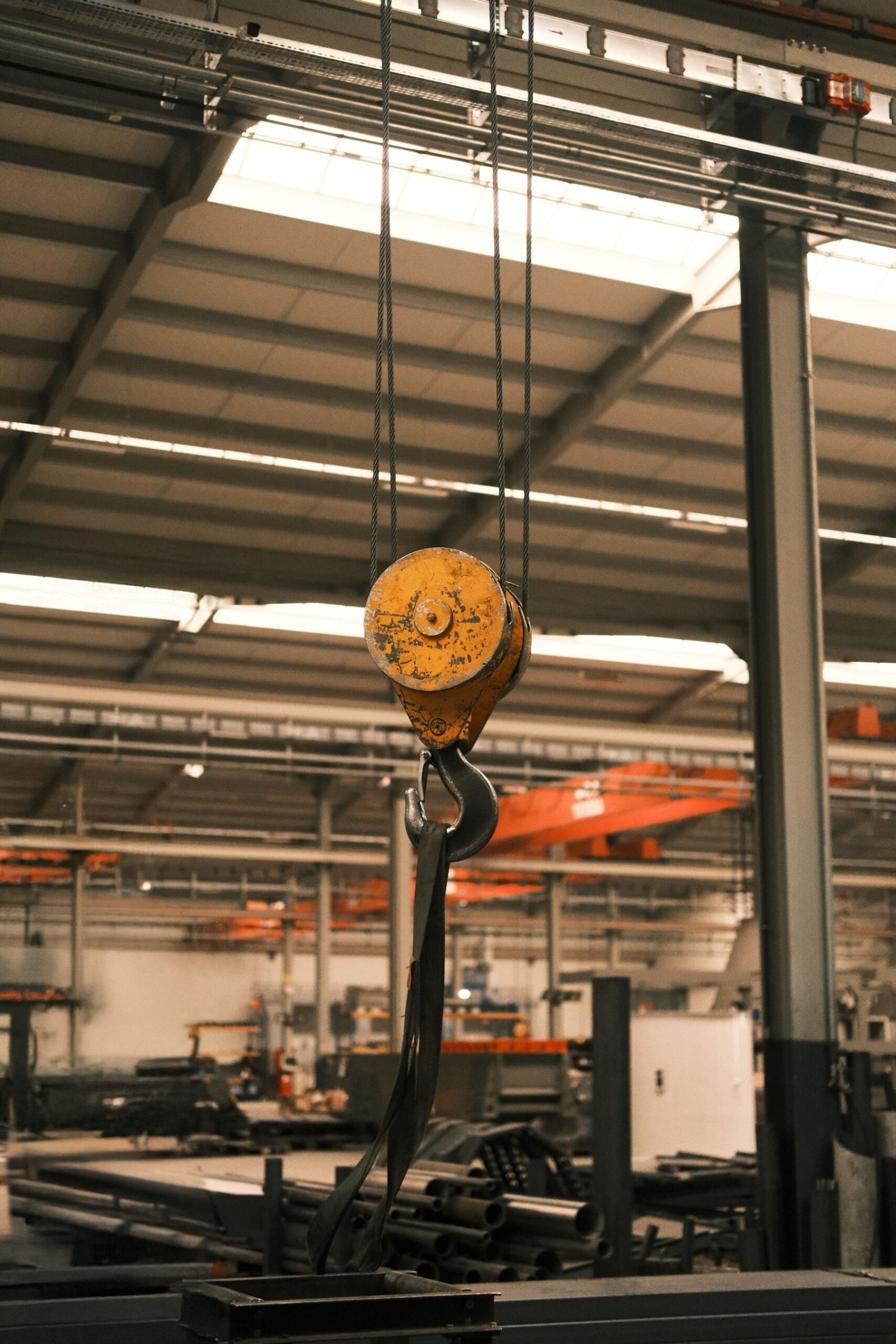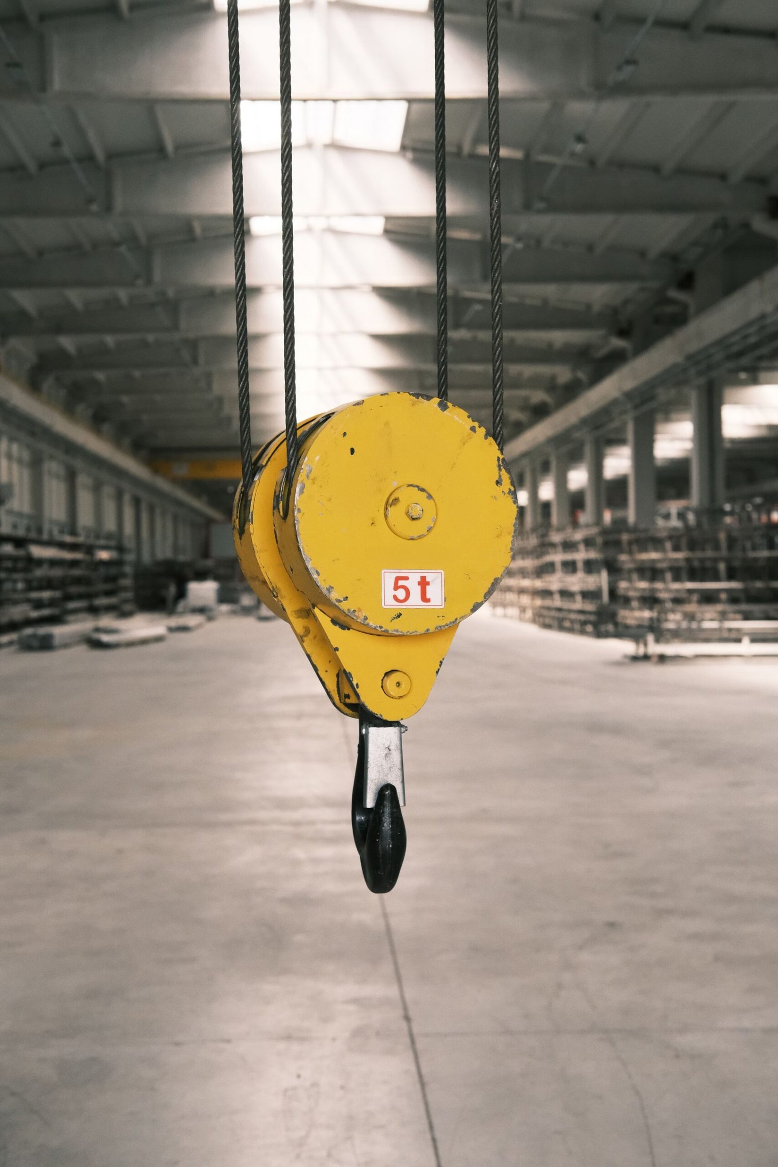
Reeving is the number that decides all the others. Parts of line is the count of rope strands hanging between the boom tip and the travelling block; divide the load by that count and you have the pull each strand carries, multiply the winch’s line pull by it and you have the load the crane can lift, minus friction. Get the count wrong and the rope is either overloaded on every lift or the crane works at half the capacity it was bought for.
Most enquiries I read say “32 mm, 200 m, one end swaged” and nothing else. The diameter usually came from the rope that was there before, and the length was guessed from the hook height. Here is the calculation I run before I quote.
What “Parts of Line” Actually Means
Most confusion comes from counting sheave passes instead of rope strands. Look up at the boom tip and count the strands running between the tip sheaves and the travelling block. That is your parts of line. Sheave count is a different number — two sheaves usually give four parts, three give six — depending where the dead end is fixed.
- The dead end counts. A rope fixed to the boom tip still supports the block, so that strand carries load.
- The lead line counts. The strand running from the tip down to the drum is one of the parts, and it carries the highest tension.
- Odd numbers exist but load the block asymmetrically — three parts on a two-sheave block hangs the hook off-centre.
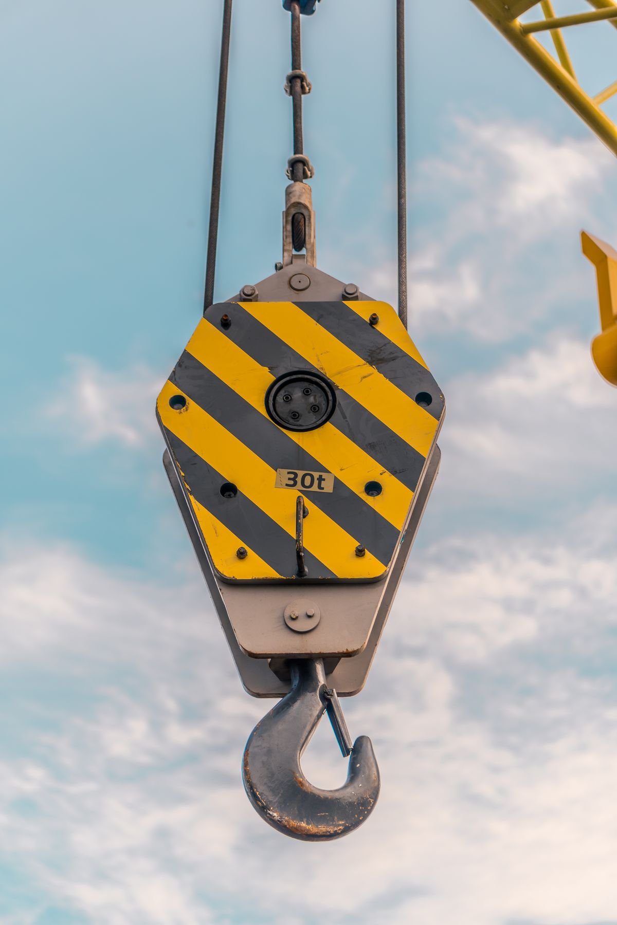
Reeving up is not free: hook speed is line speed divided by parts of line, so four parts lift at roughly a quarter of single-line speed. A crew paid by the lift will quietly drop back to two parts when the load allows — fine, provided the rope was sized for two and not for the four-part figure on the chart.
Line Pull: The Simple Version and the Honest One
The simple version is load divided by parts of line. It is good enough to sanity-check a lift and wrong by five to twelve percent at real part counts, because every sheave the rope wraps costs a few percent and the losses stack.
The honest version uses per-sheave efficiency k (about 0.98 for roller bearings, 0.96 for plain bronze) and the number of parts N. With the lead line leaving over one extra sheave, the steady pull is:
P = W × (1 − k) / [ k × (1 − kN) ] or, identically, P = W / (k + k2 + … + kN)
Reeving efficiency is W / (N × P). Table 1 does the arithmetic; the pulls are multiples of the suspended load W.
Table 1 — Line pull and reeving efficiency by parts of line
| Parts of line | Frictionless pull (W / N) | Actual pull, roller sheaves k = 0.98 | Reeving efficiency at k = 0.98 | Actual pull, plain sheaves k = 0.96 |
|---|---|---|---|---|
| 2 | 0.500 × W | 0.515 × W | 97.0% | 0.531 × W |
| 3 | 0.333 × W | 0.347 × W | 96.1% | 0.361 × W |
| 4 | 0.250 × W | 0.263 × W | 95.1% | 0.277 × W |
| 5 | 0.200 × W | 0.212 × W | 94.2% | 0.226 × W |
| 6 | 0.167 × W | 0.179 × W | 93.2% | 0.192 × W |
| 8 | 0.125 × W | 0.137 × W | 91.4% | 0.150 × W |
| 10 | 0.100 × W | 0.112 × W | 89.6% | 0.124 × W |
| 12 | 0.083 × W | 0.095 × W | 87.9% | 0.108 × W |
Adding parts pays: four to eight nearly halves the pull. But efficiency is not a rounding error when the rope is already sized at five to one — a 40 t load on four parts pulls 10.5 t on the lead line, not 10 t. None of this includes acceleration or shock either; the dynamic factor is roughly (1 + a/g), and the snatch when a load comes off the ground adds far more for a fraction of a second. That fraction is what breaks wires.
From Line Pull to Rope Diameter
With the pull in hand, the rope is a lookup plus a safety factor. Codes disagree: North American mobile crane practice works down to roughly 3.5:1 on running ropes, European partial-factor design lands nearer 4:1 to 5:1, and personnel or offshore duty goes higher. My default is 5:1, and the manufacturer’s manual overrides all of it — see breaking force, MBL and safety factor.
Table 2 — Typical MBL for 6×36WS+IWRC, grade 1960, and the line pull it permits at 5:1 (use the certificate, not this table)
| Rope diameter | Approx. MBL | Permitted line pull at 5:1 | Equivalent |
|---|---|---|---|
| 20 mm | 279 kN | 56 kN | 5.7 t |
| 22 mm | 337 kN | 67 kN | 6.9 t |
| 24 mm | 401 kN | 80 kN | 8.2 t |
| 26 mm | 470 kN | 94 kN | 9.6 t |
| 28 mm | 545 kN | 109 kN | 11.1 t |
| 32 mm | 712 kN | 142 kN | 14.5 t |
| 36 mm | 900 kN | 180 kN | 18.4 t |
Worked example: 40 t on four parts
A 40 t load (392 kN) on four parts with roller sheaves pulls 392 × 0.263 = 103 kN on the lead line. At 5:1 the rope needs 515 kN, and a 28 mm 6×36WS+IWRC at 545 kN gives 5.3:1. With plain bronze sheaves the same lift pulls 109 kN and needs 543 kN — the 28 mm is marginal, so I would quote 32 mm.
Two limits can override the arithmetic: sheave and drum diameter set fatigue life, and drum capacity sets how much rope fits. A 28 mm rope wants about a 560 mm sheave tread for a D/d of 20:1 — comfortable for a compacted rope, only adequate for a plain six-strand. If a bigger rope will not fit the drum, the answer is another pair of parts, not a harder rope. See the sheave and drum guide.
Rope Length: The Number Everyone Under-Orders
Reeving length is not hook height. The rope fills every part, reaches the drum, wraps the dead wraps, terminates at both ends and absorbs constructional stretch:
L = (N × H) + lead length + dead wraps + termination allowance, then add 3%
A 45 m hook height on four parts gives 4 × 45 = 180 m. Add 12 m from drum to boom tip, four dead wraps on a 600 mm drum (4 × π × 0.6 = 7.5 m), 2 m for two terminations and 3% for stretch and measurement error (6 m) — 207.5 m, so the order goes in at 210 m.

Two details catch people out. Constructional stretch on an IWRC rope is around 0.25%, so 200 m can grow half a metre in the first weeks — plan the termination so you can shorten rather than re-order (see the elongation guide). And check drum capacity in layers, not metres: a rope one size up adds a layer and pays off at a steeper fleet angle.
Why the Block Spins, and What Reeving Has to Do With It
Every wire rope develops torque under load; the strands try to straighten and the rope tries to unlay. On a single fall that rotates the load. On a multi-part reeving it does worse: the parts twist into a cable, the block stops hanging vertically, and the strands grind where they cross. Operators call it cabling, and once it starts you cannot lift or lower cleanly.
The controlling ratio is the length of fall divided by the spacing between parts, written L/S: short fall and wide spacing is stable, long fall with the parts bunched is not.
Table 3 — Fall-to-spacing ratio and block stability
| L/S ratio | Behaviour | What I specify |
|---|---|---|
| Below 15 | Stable with almost any construction | Six-strand or compacted rope; normal inspection |
| 15 – 25 | Manageable, sensitive to odd parts and worn sheaves | Even parts, taglines, check sheave alignment and grooving |
| 25 – 40 | Rotation likely with a six-strand rope | Category 2 or Category 1 rotation-resistant rope, even parts, shortest fall |
| Above 40 | Block rotation is the design case, not an accident | Category 1 rope (35WXK7, 35×K7); confirm against the crane maker’s stability chart |
Geometry fixes are cheaper than rope fixes, so I try them first: dead-end at the boom tip rather than the block to widen spacing, use the outermost sheaves, shorten the fall, add a tagline, keep the part count even. If it still rotates, the classes matter. Six-strand has no rotation resistance worth the name; 19×7 or 18×7 is Category 2 and helps on short falls; 35WXK7 and 35×K7 are Category 1, outer strands laid against the inner ones so the torques cancel — the rope for long falls and single-fall work.
One rule I will not bend: a swivel belongs only on a Category 1 rope. Fit one to a six-strand or Category 2 rope and you give the rope permission to unlay at the termination; the unlaid section then runs over the first sheave and stays there, with a strength loss and a spooling problem attached.
Matching Construction to the Reeving
The reeving tells you what the rope must survive: bend cycles over sheaves, torque from a free-hanging load, or crushing on a multi-layer drum. That is why the same crane model can be correctly fitted with three different ropes.
Table 4 — Construction by machine and reeving
| Machine and duty | Typical reeving | Construction I specify |
|---|---|---|
| Tower crane hoist | Single fall or two parts | 18×K7 or 35×K7 rotation-resistant, compacted, 1960 |
| Truck crane main hoist | 4 to 8 parts, variable fall | 35×K7 or 35WXK7 |
| Crawler crane, long boom and fall | 6 to 12 parts | 35WXK7; 19×7 where the fall is short and cost matters |
| Rotary drilling rig | Single or two parts, kelly and main winch | 35WXK7; 6×K36WS-EPIWRC or 8×K26WS-EPIWRC on heavy rigs |
| STS crane traction | Closed loop over traction sheaves | 4V×39S+5FC or AL FLEX-7 |
| Overhead and gantry crane | 4 to 8 parts, guided load | 6×36WS+IWRC, compacted where duty is high |
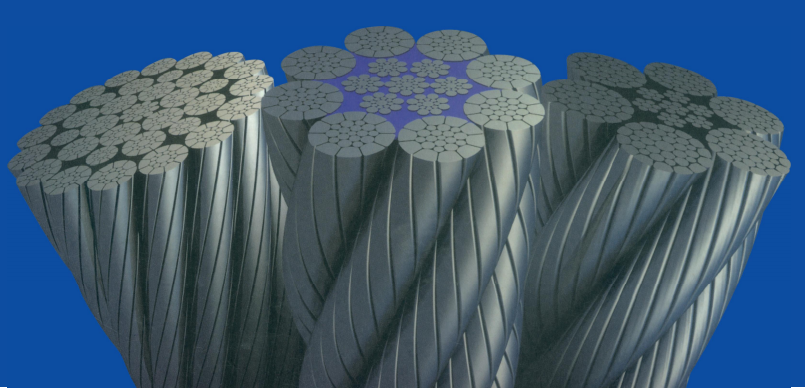
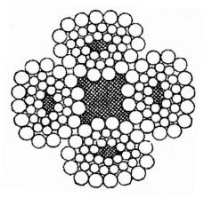
Core choice sits underneath all of this. An IWRC gives roughly 7% more breaking force than a fibre core and resists drum crushing far better, which is why almost every crane hoist rope is IWRC; fibre core still suits small winch and luffing duties. See FC, IWRC and WSC cores.

Where duty is heavy I push compaction, and where the environment is wet or abrasive, compaction plus plastic impregnation. Compaction raises the metallic area by roughly 10% at the same diameter, which buys capacity or lets you drop a size — often the only way to stay inside the drum’s layer limit.
Installation Details That Decide Whether the Math Holds
A correctly sized rope installed badly behaves like an undersized one. The list I give every customer:
- Match the lay to the drum grooving. Right-hand lay on a right-hand grooved drum. Get it wrong and the rope crosses over itself at every wrap.
- Keep back tension while spooling, around 2–5% of MBL. A loose first layer tightens later under load into crushed, uneven piles.
- Use one continuous length per reeving, and never mix an old rope with a new one. Load sharing is only equal when the ropes have the same stiffness; the new rope takes more than its share.
- Set the equalizer, where there is one — on twin reeving a mis-set equalizer doubles the load on one side.
- Break in at reduced load, re-tension as the fall stretches, and check the sheaves before the new rope goes on. A grooved-out sheave destroys it in weeks.
Inspection: Where Multi-Part Ropes Fail First
On a multi-part reeving the part you can see usually fails last. Damage concentrates where the rope never travels: the dead end at the boom tip, the equalizer sheave, the arcs sitting on the block sheaves, and the first layer on the drum. Those are the places I ask crews to open up, block landed and rope slack.
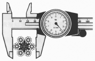
The criteria are those in ISO 4309, and they differ by construction. A six-strand rope is normally retired at ten broken wires in one lay length, or five in a single strand. A multi-strand rotation-resistant rope is far less forgiving: two broken wires in any six-diameter length, or four in any 30-diameter length, is already a discard. Diameter loss counts too — 10% gone usually means the core support has gone with it.
Record readings against part positions — 1 lead line, 4 dead end. After two or three rope changes the pattern names the bad sheave.
What I Put on the Order
Send the reeving, fall length, drum diameter and load chart page and you get a rope matched to the machine. Send a diameter and a length and you get a commodity. What I want on every order:
- Diameter, construction and core — for example 28 mm 35WXK7, compacted, IWRC
- Lay and finish — right-hand regular lay, hot-dip galvanized, lubricated
- Length with tolerance, and the number of parts it must fill
- MBF to EN 12385-4 or API 9A, with certificate; terminations at both ends
- Third-party inspection and class society, where the machine is classed
Aulone is a professional manufacturer and supplier of steel wire ropes, wire rope slings, synthetic ropes and rigging hardware for lifting, marine, mining, construction and industrial applications. We have made rope for more than twenty years, with 200,000 tons of annual capacity, stock availability on common crane sizes, and certification to EN 12385-4, ISO 9001, BV, ABS, DNV, RMRS and CE. Custom assemblies — swaged eyes, sockets, matched pairs, exact reeving lengths — are routine, and third-party testing can be arranged before shipment.
Send the reeving details with the enquiry and the rope gets matched to the machine instead of to a catalogue page: info@wireropes.net.
Frequently Asked Questions
How do I count parts of line on a crane?
Count the strands between the boom tip and the travelling block, including the dead end and the lead line. Do not count sheave passes: a two-sheave block with the dead end at the tip gives four parts, the same block with the dead end at the block gives three. Look at the machine rather than assume.
Does more parts of line always mean more capacity?
No. It increases the load the rope can share, but the block, hook, boom and load chart have their own limits, and hook speed falls in proportion. The chart says which reeving is permitted; the calculation only says whether the rope suits it.
What reeving efficiency should I use?
0.98 per sheave for roller bearings, 0.96 for plain bronze, applied cumulatively: about 95% at four parts, 93% at six, 91% at eight with good sheaves — several points worse if they are worn.
Why does my hook block spin after re-reeving?
Usually a long fall with narrow spacing, plus a rope that is not rotation resistant. Check that the part count is even, the dead end is at the tip, and the rope went in without residual twist. Above an L/S of about 25, no rigging adjustment will cure it with a six-strand rope.
Can I use a swivel with a rotation-resistant rope?
Only with a Category 1 rope such as 35WXK7 or 35×K7. On six-strand, 8×19 or Category 2 ropes a swivel lets the rope unlay at the termination, and the damage stays in the rope after the load comes off.
How much extra rope should I add for reeving and stretch?
Add 3% to the calculated length for constructional stretch and measurement error, plus a termination allowance at each end. On 200 m that is about 6 m — far cheaper than a second order and a lost day.