The short answer: wire rope drum capacity is layer arithmetic. Measure the barrel diameter D, the usable width W between the flanges, the flange height and the actual rope diameter d; then count wraps per layer (W ÷ d) and add up one lap length per layer, because every layer’s pitch diameter grows by two rope diameters. Deduct the dead wraps that must never leave the drum and a spooling allowance of 5–10%, and you have the usable length. Get it wrong in the direction of “just a bit more rope” and the excess climbs the flanges, tangles, and in the worst cases takes an arm with it.
In eleven years of specifying rope I have seen this calculation done properly perhaps half the time. Usually the rope fits. When it does not, the failure is spectacular: I still remember the fishing-vessel incident report from Newfoundland where a crew replaced a worn rope with the same length of a larger diameter, the drum could not hold the extra volume, loops spilled over the flange during operation, and a deckhand lost his forearm trying to push them back. That hazard report is the reason I answer every “will this rope fit my drum?” question with arithmetic, not with a shrug. Here is the method I use, plus the margins that keep it honest.
Why Drum Capacity Is a Safety Calculation, Not a Storage Problem
A drum that is overfilled does not politely refuse the last wraps. The rope piles above the flange, upper layers slice down through lower ones under load, and a crossover under tension can pinch and snap strands. Loose or crossed spooling also lets the rope cut down into itself, which crushes the core and shows up later as internal damage your ISO 4309 inspection will flag long before the rope’s design life is reached. Capacity, spooling quality and rope life are one subject, not three.
The other direction matters just as much. Rope that is sized generously on paper but specified with too little margin for dead wraps and imperfect winding leaves the winch short of working travel — which on a drilling rig or a crawler crane means the hoist stalls with the load in the air.
The Measurements You Need Before Any Formula
Everything below assumes five numbers you can take with a tape and a rope datasheet. Measure the rope, do not trust the nominal — actual diameter typically runs a few percent over nominal, and compacted ropes measure differently again.
Table 1 — The five inputs of a drum capacity calculation
| Symbol | What it is | Where to measure | Watch out for |
|---|---|---|---|
| D | Barrel (drum) diameter | Surface of the bare barrel, not over old rope | Grooving adds a little; measure over the groove root |
| W | Usable width between flanges | Inside face to inside face | Keep clear of the flange welds; deduct rope anchor hardware |
| A | Flange height above barrel (rope space) | Barrel surface to flange top | The top layer must stay below the flange — see freeboard below |
| d | Actual rope diameter | Measure across strand crowns, two directions | Actual runs larger than nominal; use the bigger number |
| n | Dead wraps | Turns that stay anchored on the drum | 2 minimum by most standards, 3 in common practice |

The Layer-by-Layer Method (the Accurate Way)
The physically honest method walks up the drum one layer at a time. It takes five minutes and it never lies to you.
Step 1 — Wraps per layer
N = W ÷ d, rounded down. A partial wrap across the drum is a crossover waiting to happen, so it does not count.
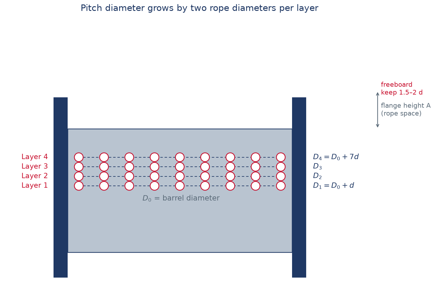
Step 2 — Pitch diameter of each layer
The first layer sits on the barrel, so its centreline is one half rope-diameter above the barrel surface on each side: D₁ = D + d. The second layer sits in the valleys of the first, lifting the centreline a full rope diameter, and so on. In general, for layer k:
Dᵣ = D + d × (2k − 1)
Every layer adds two rope diameters to the pitch diameter — which is why the outer layers hold so much more rope per lap, and also why line pull falls as the rope builds.
Step 3 — Length per layer, and the total
Each layer stores N laps of circumference π × Dᵣ:
Lᵣ = N × π × Dᵣ (keep everything in metres: divide the diameters by 1000)
Add layers until you reach the flange. Then stop and check the freeboard: the top of the rope stack must sit at least 1.5 to 2 rope diameters below the flange top. If it does not, the last layer does not exist, no matter what the arithmetic says.

Worked example: 22 mm rope on a rig-style winch
Here is a real enquiry shape: a rotary drilling rig winch, barrel D = 460 mm, usable width W = 660 mm, flange diameter 700 mm, and the customer wants a 22 mm 6×36WS+IWRC hoist rope.
- Wraps per layer: N = 660 ÷ 22 = 30
- Layer 1: D₁ = 482 mm → 30 × π × 0.482 = 45.4 m
- Layer 2: D₂ = 504 mm → 47.5 m
- Layer 3: D₃ = 526 mm → 49.6 m
- Layer 4: D₄ = 548 mm → 51.6 m
- Four layers, gross: 194.1 m
Now the honest part. Flange height above the barrel is (700 − 460) ÷ 2 = 120 mm. Four layers of 22 mm rope stand 88 mm high, leaving 32 mm of freeboard — about 1.5 rope diameters, the bare minimum, so four layers is the ceiling and I would log it as a watch item. Deduct three dead wraps on the first layer (3 × 1.51 m ≈ 4.5 m) and you have about 189.6 m. Apply a 5% spooling allowance on a well-grooved drum and the usable figure is roughly 180 m; on a plain drum in rough field service, allow 10% and quote about 171 m. That gap between 194 m on the calculator and 171 m in the field is where most disappointments live.
The Quick Volume Formula (the Fast Way)
For quoting and sanity checks, the metal-trade handbook formula estimates the whole drum in one line. In imperial units:
L (ft) ≈ 0.262 × (D + A) × A × B ÷ d²
where D is barrel diameter, A the rope space depth to the flange top, B the width between flanges and d the rope diameter, all in inches. The 0.262 constant is π ÷ 12 with a deliberately conservative packing assumption folded in. In metric, the same annulus-volume logic gives L (m) ≈ 3.14 × (D + A) × A × B ÷ d² with all dimensions in millimetres. The layer-by-layer method is more accurate; the volume formula is faster and errs on the safe side.
The formula’s most useful property is what it says about diameter. Capacity falls with the square of rope diameter:
Table 2 — Capacity of the same drum (D = 24 in, A = 12 in, B = 48 in) by rope diameter
| Rope diameter | Approximate capacity | Relative to 1 in |
|---|---|---|
| 1/2 in | ≈ 21,700 ft (6,620 m) | ×4 |
| 3/4 in | ≈ 9,660 ft (2,940 m) | ×1.78 |
| 1 in | ≈ 5,430 ft (1,655 m) | ×1 |
| 1-1/4 in | ≈ 3,480 ft (1,060 m) | ×0.64 |
| 1-1/2 in | ≈ 2,410 ft (735 m) | ×0.44 |
| 2 in | ≈ 1,360 ft (415 m) | ×0.25 |
Double the rope diameter, quarter the capacity. That single line answers most “can I upsize my rope?” enquiries before they become orders.
What Eats Your Capacity in the Real World
The calculated figure is a ceiling. These are the deductions I apply before I call a length usable:
Table 3 — The deductions between calculated and usable capacity
| Deduction | Typical allowance | Why |
|---|---|---|
| Dead wraps at the anchor | 2 wraps minimum, 3 in practice, 4–5 on towing and offshore winches | These turns never leave the drum and protect the anchor; they are not working rope |
| Spooling imperfection | 5% grooved drum with good fleet angle; 10% plain drum or rough service | Crossing, gaps and loose wind consume width that the arithmetic assumes is perfect |
| Flange freeboard | Keep top layer 1.5–2 d below flange top | Rope above the flange is rope that can spill, pinch and fail |
| Spooling tension deficit | Wind on under tension, about 1–2% of rope MBL | Slack wind lets upper layers cut down into lower ones under load |
| Rope diameter tolerance | Use measured, not nominal, diameter | Actual diameter runs over nominal; on a 30-wrap layer, one extra millimetre costs a wrap |
Fleet Angle: The Capacity Killer Nobody Measures
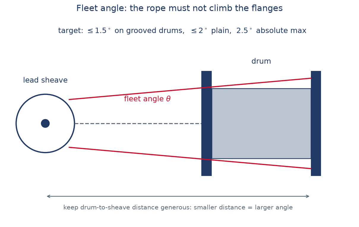
Fleet angle is the angle between the rope’s natural line from the drum to the first sheave and the drum’s axis of rotation. Too steep, and the rope climbs the flange or piles up at the drum edges instead of lying in the layer — effectively shrinking your usable width and shortening rope life at the same time. Most winch makers quote 1.5° as the target for grooved drums and 2° for plain drums, with 2.5° an absolute ceiling. The geometry is simple: the closer the sheave sits to the drum, the steeper the angle, so when a customer reports crossovers near the flanges, the first thing I ask for is the drum-to-sheave distance. Full sheave and drum geometry, including D/d ratios, is in my sheave and drum guide.
Line Pull Drops as the Rope Builds Up
One more consequence of that growing pitch diameter: the winch’s pull falls layer by layer. Hoisting torque is fixed by the drive, so line pull equals torque divided by the pitch radius — and the pitch radius grows. In the worked example above, the radius grows from 241 mm on layer 1 to 274 mm on layer 4, so the winch pulls about 12% less rope force on the top layer than on the first, even before any drive efficiency losses. When a customer tells me the winch is rated “150 kN”, I always ask: first layer or full drum? The answer changes which rope diameter I quote. This is the same arithmetic that decides parts of line and line pull in my reeving guide, just applied at the drum instead of the sheaves.
Choosing Rope That Suits a Multi-Layer Drum
Capacity arithmetic assumes the rope spools the way the formula imagines. Some constructions cooperate; some fight the drum. On multi-layer drums the rope’s worst enemy is layer-crossing crush — every upper layer sits in the valleys of the lower one, and at each crossover the pressure localizes. That is why I steer multi-layer duty toward steel-core, and usually compacted, rope:
Table 4 — Rope construction by machine, for drums that wind multiple layers
| Machine | Construction I specify | Why it suits multi-layer drums |
|---|---|---|
| Rotary drilling rig main winch | 35WXK7-EPIWRC; 6×K36WS-EPIWRC / 8×K26WS-EPIWRC on heavy rigs | Rotation-resistant, steel core, plastic-impregnated against internal wear; see the rotary rig rope guide |
| Truck and crawler crane hoist | 35×K7 / 35WXK7 | Rotation-resistant with crush-resistant steel core |
| Tower crane hoist | 18×K7 / 35×K7 | Rotation-resistant for single-fall and two-fall reeving |
| Overhead and gantry cranes | Compacted 6×36WS class, IWRC | Compaction packs more steel into the same diameter and resists crossing crush; see the compacted rope guide |
| Marine and towing winches | 6×36WS class, galvanized, IWRC | Long layered storage plus corrosion exposure |
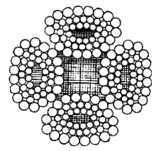
One practical note that ties it together: because a compacted rope packs more steel into the same nominal diameter, it also stores slightly more breaking force per millimetre of drum space — on a drum-limited machine, compaction is often worth more than a diameter upsize that will not fit.
Before You Order, Run the Numbers Twice
When you enquire for rope, send the drum dimensions with the rope specification — barrel diameter, usable width, flange height, required working length, and how many layers the machine manufacturer allows. It takes you two minutes and it lets us confirm the length, flag a freeboard problem, and propose a compacted alternative if the drum is the limiting factor. Aulone is a professional manufacturer and supplier of steel wire ropes, wire rope slings, synthetic ropes and rigging hardware for lifting, marine, mining, construction and industrial applications. We have made rope for more than twenty years, run 200,000 tons of annual capacity, keep stock of common crane and winch sizes, and certify to EN 12385-4, ISO 9001, BV, ABS, DNV, RMRS and CE. Custom cut lengths, sockets and swaged assemblies are routine, and third-party testing can be arranged before shipment.
Send the drum drawing or just the measurements, and we will confirm the length that actually fits: info@wireropes.net.
Frequently Asked Questions
How many dead wraps must stay on the drum?
Most standards and machine directives require at least two full wraps to remain on the drum under every operating condition; three is common good practice, and towing, anchor-handling and offshore winches typically carry four to five because shock loads make the anchor wraps work harder. Dead wraps are never counted as working length.
What is the maximum fleet angle for wire rope on a drum?
Aim for 1.5° or less on grooved drums and 2° on plain drums; treat 2.5° as an absolute ceiling. Beyond those angles the rope climbs the flanges and piles at the drum edges instead of spooling into clean layers, which wastes capacity and damages the rope. Specialized grooving systems relax the limit slightly — ask the drum manufacturer.
Does drum grooving change the capacity?
Not the nominal capacity — the same rope volume fits either way. Grooving changes how much of the capacity is usable: a grooved drum spools square and orderly, so the 5% spooling allowance is realistic instead of optimistic. On a plain drum, expect the full 10% deduction and more if the winch sees shock loads.
Why does line pull decrease on the top layers?
The winch drive delivers a fixed torque, and line pull equals torque divided by the pitch radius of the rope on the drum. Because each layer’s pitch diameter grows by two rope diameters, a four-layer build-up can leave the top layer pulling roughly 10–15% less force than the first. Always specify whether a winch rating applies to the first layer or the full drum.
Can I fit a longer rope by winding it tighter or filling to the flange?
No — and this is the mistake behind real amputation injuries. Slack wind cuts down under load, rope stacked above the flange can spill and pinch, and a drum filled to the last metre has no margin for the imperfect spooling that always arrives with the rope. Wind on under tension, respect the freeboard, and take the spooling allowance seriously.
Can I replace my rope with a larger diameter on the same drum?
Only after running the numbers. Capacity falls with the square of diameter, so a 10% larger rope costs about 19% of the length — the Newfoundland incident behind this article started exactly that way. Check the new freeboard, the sheave D/d ratio, the drum’s line pull at the new radius, and whether the higher breaking force is actually needed. If the drum is the constraint, a compacted rope at the original diameter is usually the better answer.