The short answer: most drum winders run a triangular (flattened) strand or full locked coil winding rope sized for a minimum static factor of safety of 6.5, while multi-rope friction (Koepe) winders deeper than about 1,000 m demand rotation-resistant constructions — and balance and guide ropes are selected at roughly 5:1. Pick the construction from the winder type and the shaft depth first; surface finish, core and lay direction follow from the water and the duty. A mine hoist rope carries people, runs millions of repetitive cycles, and sits under an inspection regime no crane rope ever sees. Here is how I approach selection, installation and retirement when a mine asks for winding ropes.
The Four Rope Duties in a Shaft Winding System
A vertical shaft is not one rope problem, it is four or five. The head rope gets the glory, but the balance rope hanging in a U-loop at the shaft sump and the guide ropes running the full shaft depth have their own failure modes and are frequently specified as an afterthought. Get each duty clear before you talk construction:
| Rope | What it does | Typical construction | Deciding factor |
|---|---|---|---|
| Head / winding rope (drum winder) | Lifts cage or skip, spooled onto a multi-layer drum | Triangular strand 6-strand, full locked coil, or multi-strand rotation-resistant | Static safety factor and multi-layer drum crushing |
| Head rope (friction / Koepe winder) | Drives the conveyance by grip on a lined friction sheave | Triangular strand (<1,000 m), rotation-resistant multi-strand or locked coil (deep shafts) | Traction, consistent diameter, low torque for load sharing |
| Balance (tail) rope | Connects the bottoms of the two conveyances to offset winding-rope weight | 34×7 / 34×17 / 34×19 multi-strand, or flat plastic-covered rope | Flexibility to form the sump loop; must not transmit torque |
| Guide rope | Guides the conveyance in rope-guided shafts | Half-lock coil (full-lock coil in some installations) | Straightness and wear resistance at guide shoes |
| Sinking rope | Kibbles and sinking stages during shaft construction | Rotation-resistant multi-strand, mandatory as depth grows | Rotation resistance under a freely hanging load |
Drum Winder vs Friction Winder: Why the Machine Decides the Rope
The first question I always ask a mine is not “what diameter?” but “which winder?” — the two machine families load a rope in completely different ways.
A drum winder spools the rope onto a cylindrical drum, usually in multiple layers. Multi-layer spooling means every wrap that ends up under another layer gets crushed, so crushing resistance and a smooth, compacted outer surface matter enormously. The conveyance hangs from a single (or double) rope and can swing, so torque behaviour matters too — ordinary lay is generally preferred over Lang’s lay unless the installation is designed for it. A minimum of three complete dead coils must stay on the drum at all times, and the rope order length must include allowance for cropping throughout the rope’s life.
A friction winder (Koepe) passes the rope over a powered sheave lined with a friction material and drives it by grip alone, in a traction loop with the balance side. That changes everything: the rope needs a very consistent diameter to grip the lining, low constructional stretch to keep tension balance between multiple head ropes, and — critical on deep shafts — low torque, because multi-rope load sharing collapses if one rope torques differently from its neighbours. Rope load balancing and equal sheave circumferences make or break rope life on multi-rope friction winders, which is why for depths beyond roughly 1,000 m, rotation-resistant or locked coil constructions become the sensible default rather than an option.
Between the two sits the Blair multi-rope arrangement, which runs two ropes in parallel grooves of a single drum — a good compromise when a single rope of the required breaking force would be impractically large to handle and cap.
Choosing the Construction
Winding ropes are engineered products in a way that ordinary crane ropes are not — they are manufactured to dedicated mine-hoisting standards (EN 12385-6 for stranded ropes, EN 12385-7 for locked coil ropes) and the big constructions have earned their places over a century of service.
| Construction | Strengths | Watch-outs | Typical use |
|---|---|---|---|
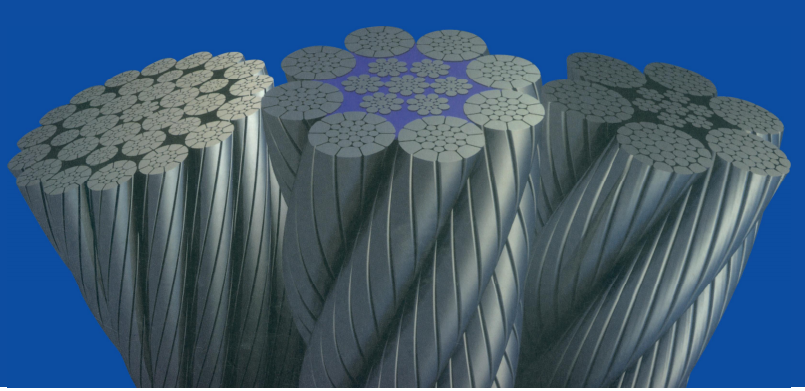
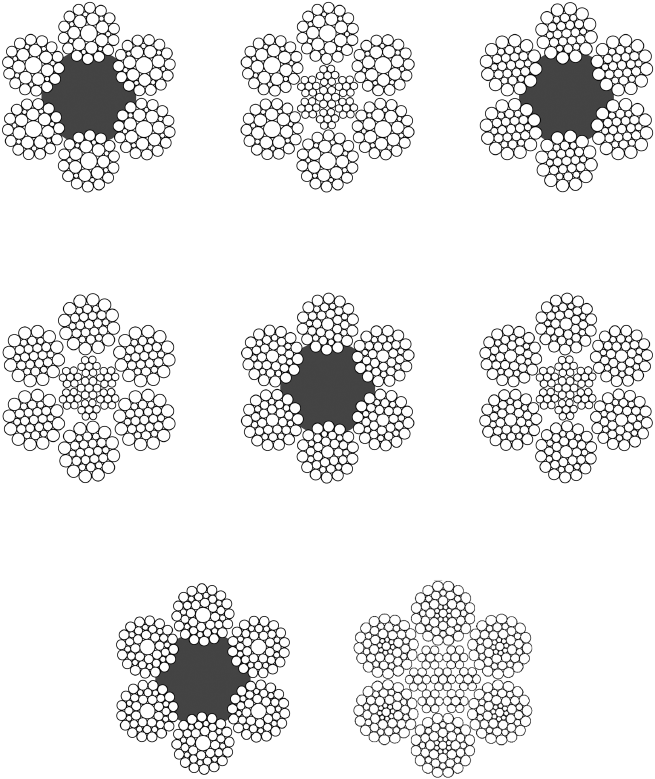
| Triangular (flattened) strand, 6-strand | Flat bearing surface — about 4× the wear area of round strand; ~10% stronger than the same diameter standard 6-strand; very crush-resistant | Stiffer handling than round strand; needs competent capping | Drum and Koepe head ropes, slope winders, depths to ~1,000 m |
| Full locked coil | Smooth sealed surface, excellent corrosion and wear behaviour, high metallic area, minimal rotation | Less flexible; unforgiving of kinks and rough handling; grades 1570–1960 N/mm² (round wires) | Deep friction winders, guide ropes where high stiffness is acceptable |
| Half locked coil | Semi-sealed outer surface, good wear resistance with more flexibility than full lock | Less smooth than full lock | The default guide rope construction |
| Multi-strand rotation-resistant (34×7 / 34×17 / 34×19 / 35×7 class) | Very low torque, flexible, tolerant of deep free-hanging duty | Higher constructional stretch; vulnerable to birdcaging if misused; needs strict handling discipline | Deep Koepe head ropes, balance ropes, shaft-sinking kibble ropes |
| Compacted round strand (6×K36 class) | +10–15% breaking force for the same diameter, smooth spooling, good with plastic-impregnated cores | Confirm the compaction and core specification in writing | Drum winders and modern friction installations where a round strand is preferred |
Sizing the Rope: Static Safety Factor and the Maximum Suspended Load
Winding ropes are sized on the static factor of safety: the minimum breaking force of the rope divided by the maximum suspended load in the most heavily loaded part of the rope — normally just below the headframe pulley or sheave, with the fully loaded conveyance at pit bottom. The maximum suspended load is the sum of the loaded conveyance, all attachments (chains, links, detaching hook, cappings), the weight of rope hanging below the headframe, the balance rope hanging below that conveyance, and half the weight of any sheaves running in the balance-rope loop. For multi-rope winders, divide by the number of head ropes.
Why is the factor so generous compared with crane work? Winding shocks during acceleration and speed changes can push the live load to about 1.5 times the static value, bending over headframe and deflection sheaves adds secondary stresses, and the rope loses strength gradually in service. The generous static margin absorbs all of that.
| Application | Minimum static factor of safety | Source / practice |
|---|---|---|
| Drum winding of persons (UK) | 6.5 | UK Deep Mined Coal ACOP guidance |
| Man-cage or kibble winding | 7.5 − 0.001 L (L = shaft depth in m) | Queensland QGN 30.2 shaft-sinking guidance |
| Winding of persons | > 6 | Ghana Minerals & Mining Regulations L.I. 2182 |
| Winding of rock / materials | 5.5 − 0.0003 D (D = depth of wind in m) | Ghana L.I. 2182 |
| Rock winding in a rock-only shaft | > 4.5 | Ghana L.I. 2182 |
| Balance ropes and guide ropes | ≈ 5:1 | Widespread industry practice |
A worked example
Take an 800 m coal shaft with a drum winder. The loaded skip comes to 35.2 t (14 t tare + 20 t payload + 1.2 t of attachments), and 820 m of 38 mm rope hangs below the headframe pulley at about 5.9 kg/m, adding 4.8 t. Maximum suspended load: 40 t. At the 6.5 minimum, the rope must deliver at least 260 t ≈ 2,550 kN of breaking force. A single rope of that strength lands in the ~55 mm class; a two-rope Blair arrangement shares the load, so each rope needs about 1,275 kN — roughly a 38 mm triangular strand at 1960 N/mm². Add up the suspended weight, apply the factor, and let the tables pick the diameter.
Cores, Finish and Compaction for Winding Duty
Core: an independent wire rope core (IWRC) is the default for winding ropes — it resists crushing on multi-layer drums and keeps the rope dimensionally stable. On wet shafts, a plastic-impregnated core (EPIWRC) is worth specifying: the polymer sheath between strand layers locks the factory lubricant in and keeps shaft water out, which measurably slows internal corrosion — the invisible killer in winding ropes.
Finish: bright (ungalvanised) rope is acceptable only in dry, non-corrosive shafts. Wet, humid or acidic conditions — which is most mines — call for hot-dip galvanised rope; locked coil ropes can be supplied with all layers galvanised or just the outer two or three. Galvanising does not excuse lubrication: galvanised ropes need the same disciplined re-lubrication as bright ones.
Lay: ordinary lay resists rotation better than Lang’s lay and is the standard choice for winding; Lang’s lay buys superior bending fatigue but only where rotation is properly constrained. Where bending fatigue dominates, equal-lay constructions and compacted strands are the upgrades I discuss first with the winder engineer.
Balance and Guide Ropes Get Their Own Rules
The balance rope must be flexible enough to bend under its own weight into the U-shaped sump loop between the two conveyance suspension points, so flexibility — not raw strength — drives the construction choice, and multi-strand or flat constructions dominate. A plastic outer cover is highly effective at keeping slurry and water out of the rope interior, and the balance rope’s weight should be engineered against the winding rope so the system stays balanced.
Guide ropes are standing ropes: their enemies are wear at the guide shoes, straightness (a rope that will not sit straight will not guide straight), and corrosion. Half-lock coil is the common answer. They are tensioned, not reeved, so inspection focuses on wear zones and the tensioning arrangement rather than bending fatigue — and some winding standards allow guide ropes a higher loss-of-metallic-area limit than head ropes precisely because they do not bend.
Installation: Capping, Spooling and Dead Coils
Nothing in mining rope work punishes shortcuts like installation and capping. The rules I insist on:
- Unreel correctly — rope off the reel in the same direction it was spun on, with 2–5% back tension, never off a loose coil that can kink.
- Seize before cutting — a cut rope that unravels has lost its preformation permanently.
- Cap by the book — white-metal or resin cappings fitted by competent persons to the OEM procedure (and to the applicable standards such as AS 3637.3 for rope cappings). If the integrity of an existing capping cannot be confirmed, the rope comes out of service — that is how seriously the regulations treat it. Never re-use a capping socket or wedge set from the old rope.
- Spool under tension with correct fleet angle, and keep at least three dead coils on the drum.
- Allow for stretch — expect roughly 0.25% constructional stretch on an IWRC rope before it stabilises, and order length with cropping allowance so wear zones can be moved during the rope’s life.

Inspection and Discard: What Winding Standards Actually Require
Mine winding ropes live under a stricter regime than any crane rope. Visual inspection is backed by electromagnetic (EM/MRT) non-destructive testing — loss of metallic area (LMA) and broken-wire detection — and in jurisdictions such as Australia, AS 4812 sets the discard criteria for drum, friction, balance, rubbing and guide ropes. The 2023 edition added locked coil and plasticised-core coverage, moved inspection frequency to a cycle-based basis, and increasingly accommodates continuous condition monitoring.
The numbers below come from the NSW Resources Regulator’s powered-winding technical reference guide, which mirrors AS 4812 thinking. Retire the rope if any of these occur:
| Criterion | Threshold |
|---|---|
| Broken wires in one rope lay — non-uniform | Loss of metallic area > 5% |
| Broken wires in one rope lay — uniform | Loss of metallic area > 8% |
| Broken wires in any one strand lay | > 15% of the strand’s total wires, or > 40% of the strand’s outer wires |
| Five adjacent lay lengths | More than double the single-lay broken-wire limit |
| Valley (inter-strand) wire breaks | More than one visible in a rope lay |
| Near terminations | More than one broken wire within 1 m of any termination |
| Outer wire wear | Outer wire diameter reduced by more than one third over at least two lays |
| Rope diameter | Reduction > 6% from nominal |
| EM testing (LMA) | > 6% loss (never > 10%; guide ropes may exceed 12% only with written competent-person approval) |
Two points I always stress to inspection teams. First, valley breaks and breaks near terminations are the loudest alarms on a winding rope — they indicate structural deterioration, not surface wear, and they rarely occur alone. Second, discard criteria are minimums, not a pass list: a combination of individually sub-threshold faults can still make a rope unfit. The competent person’s judgement sits above every table, and a documented trend from previous EM tests is often what triggers retirement before any single limit is crossed. For the general visual criteria that apply across rope types, our ISO 4309 inspection guide is a useful companion.
Rope Records: The Quiet Discipline That Extends Life
Winding regulations expect a rope history for every rope in the system, and in twenty years I have never seen a mine regret keeping good records — only ones that regretted the gaps. At minimum: the manufacturer’s certificate with the actual breaking-force results, the installation date, every cropping date, every NDT result with its date, and any sample removed for destructive testing. On multi-rope friction winders, also log individual rope load monitoring — load imbalance is the leading indicator of trouble. When the EM trend line and the cycle count from previous ropes line up, you order the replacement on your schedule, not the shaft’s.
Final Word
Mine hoist rope selection is a system decision, not a catalogue decision: winder type and depth choose the construction, the suspended-load calculation chooses the diameter, the water chooses the finish and core, and the regulations choose the inspection regime. When comparing suppliers, ask specifically for winding-grade ropes manufactured to EN 12385-6 or EN 12385-7 with lot-certified breaking-force results, and ask how they handle capping compatibility and custom lengths with fused and tapered ends — that is where field problems usually start.
Aulone is a professional manufacturer and supplier of steel wire ropes, wire rope slings, synthetic ropes and rigging hardware for lifting, marine, mining, construction and industrial applications. With more than 20 years of manufacturing experience, an annual capacity of 200,000 tons, stock availability on common constructions, and certifications including EN 12385-4, ISO 9001, BV, ABS, DNV, RMRS and CE, we supply custom-length winding assemblies with full documentation and third-party testing on request. Send your shaft data — depth, conveyance mass, payload and winder type — to info@wireropes.net and our engineers will come back with a sizing proposal.
Frequently Asked Questions
What construction is best for a mine hoist rope?
For drum winders, triangular (flattened) strand is the proven default thanks to its large wearing surface and crush resistance, with full locked coil on deep or corrosion-critical installations. For friction winders, triangular strand works well below about 1,000 m; deeper shafts generally move to rotation-resistant multi-strand or locked coil constructions so multi-rope load sharing stays stable. The winder type and depth decide.
What safety factor do mine hoist ropes need?
It depends on the jurisdiction and the duty, but figure on a minimum static factor of 6.5 for drum winding of persons under UK guidance, formulas around 7.5 − 0.001L for man-cages in Australian shaft-sinking guidance, and roughly 5:1 for balance and guide ropes. Always check the mining regulation that governs your shaft — the numbers differ by country and by whether people are being wound.
How long does a mine hoist rope last?
Life is counted in winding cycles, not years, and it varies hugely with depth, payload and water: the same construction that lasts years on a shallow shaft can be retired in months on a deep, wet one. Track bank-to-bank cycles per rope, run EM testing on a cycle-based schedule, and let the discard criteria make the retirement decision.
Why are balance ropes often plastic-covered?
Because they live in the wettest, dirtiest part of the shaft. A plastic outer cover seals water and abrasive slurry out of the rope interior, while the multi-strand or flat construction gives the flexibility the sump loop demands. For round balance ropes, a plastic-filled construction between the strands serves the same purpose.
How often should winding ropes be inspected?
Visually at the frequency your shaft regulations and site rules set — typically daily or per shift for the accessible zones — plus scheduled EM/MRT testing at cycle-based intervals under standards such as AS 4812. Rope-guided shafts should include guide rope wear checks at the guide shoes, and terminations should be examined visually or by x-ray, since EM instruments struggle within about a metre of a capping.
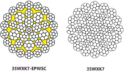
Can I use a crane wire rope, like 35xK7, as a winding rope?
I would not. Winding ropes are manufactured to dedicated mine-hoisting standards (EN 12385-6 and -7) with constructions, tolerances and capping compatibility engineered for shaft duty, and the regulations expect a matching certificate. A crane rope of the right diameter will not carry the right paperwork, and its rotation and stretch behaviour were never designed for a winder. Specify a winding-grade rope and keep the certificate with the rope history. (For the crane-side constructions, see our guides on tower crane and truck crane rope.)