Wire Rope Sling Angle: How a Shallow Angle Multiplies Your Load
A wire rope sling does not get weaker when you rig it at an angle — the geometry simply demands more from it. The tension in each leg equals its share of the load divided by the sine of the angle from horizontal, so at 60° each leg carries about 15% more than its share, at 45° about 41% more, and at 30° each leg of a two-leg sling carries the entire load. ASME B30.9 does not permit rigging below 30° from horizontal, so the fastest way to stay safe is to keep the legs steep, run the tension math before every bridle, and let the sling tag have the final word.
I have spent a lot of years quoting wire rope slings, and the same conversation repeats every month. A buyer asks for slings “rated for 10 tons” for a two-leg lift of a 10-ton machine, and the honest answer is that no sling rated 5 tons per leg will do that job at a shallow angle. The rope does not care what the load weighs — it cares what the geometry makes it carry.
Why the Angle Changes What Each Leg Carries
When a sling leg hangs vertical, all of its tension works straight up against gravity. The moment the leg leans outward, the tension splits into two components: a vertical component that supports the load and a horizontal component that pulls the legs toward each other. To still deliver the same vertical support, the total tension has to grow:
Tension per leg = (Total load ÷ number of legs sharing) × (1 ÷ sin θ)
where θ is the leg angle measured from the horizontal. The factor 1 ÷ sin θ is called the load angle factor or tension multiplier. A vertical leg has sin 90° = 1.000, so the factor is 1. A leg at 30° has sin 30° = 0.500, so the factor is 2.000 — each leg now carries twice its vertical share, which for a symmetric two-leg sling means each carries the entire load.
Some crews prefer to work the other direction — derating the sling instead of multiplying the load. Both routes land on the same answer; run whichever your crew will actually use.
The Sling Angle Factor Chart
The table below is the one I keep taped inside my notebook. It covers the angles you will actually meet on site, with the tension each leg of a two-leg sling carries under a 10,000 lb load. If your measured angle falls between two rows, always use the next lower angle — conservative, and cheaper than a dropped load.
| Angle from horizontal | Load angle factor (1 ÷ sin θ) | Effective capacity vs. vertical rating | Tension per leg, 2-leg lift of 10,000 lb |
|---|---|---|---|
| 90° (vertical) | 1.000 | 100% | 5,000 lb |
| 75° | 1.035 | 96.6% | 5,176 lb |
| 60° | 1.155 | 86.6% | 5,774 lb |
| 50° | 1.305 | 76.6% | 6,527 lb |
| 45° | 1.414 | 70.7% | 7,071 lb |
| 40° | 1.556 | 64.3% | 7,780 lb |
| 35° | 1.743 | 57.4% | 8,717 lb |
| 30° (minimum) | 2.000 | 50.0% | 10,000 lb |
| Below 30° | Not permitted per ASME B30.9, unless recommended by the sling manufacturer or a qualified person | ||
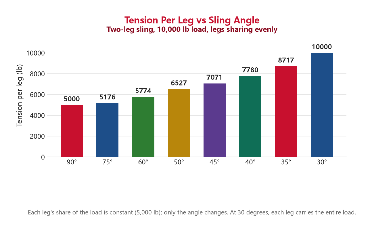
Notice where the curve steepens. Going from 90° to 60° costs you 13% of capacity; going from 45° to 30° costs another 29% in a few degrees of headroom. That jump is what catches crews out — a bridle that looks only “a bit flatter” than yesterday’s lift can have doubled the tension in every leg.
How to Calculate Leg Tension — Three Ways
The standard formula
Tension per leg = (load ÷ legs sharing) × (1 ÷ sin θ). A 12-ton machine on a symmetric two-leg bridle at 45°: each share is 6 tons, the factor is 1.414, so each leg carries 8.5 tons. If your slings are rated 6.5 tons vertical, the lift is over — steeper geometry, longer slings, or bigger rope. Round the calculated tension up to the next available rating, never down.
The tape-measure method
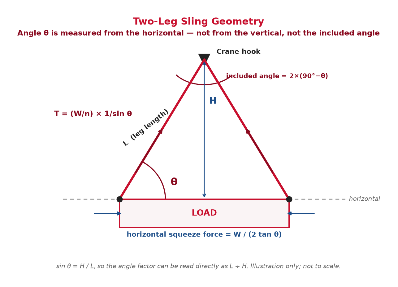
You do not need a protractor on the crane deck. Because sin θ = H ÷ L, the angle factor is simply L ÷ H, where L is the leg length from hook to attachment point and H is the vertical height from the hook to the pick points. Legs 4.0 m long with 2.8 m of headroom give L ÷ H = 1.43 — about a 44° angle — so each leg of a two-leg lift of an 8-ton load carries ≈ 5.7 tons. Tape two distances, multiply, done. (Alternatively, derate the sling: effective WLL at angle = vertical WLL × sin θ. Same answer, whichever your crew will actually apply under pressure.)
The Convention Trap: Horizontal, Vertical, or Included?
More rigging errors start here than anywhere else. The same lift can be described three ways, and mixing the conventions produces answers that are dangerously optimistic. Charts in most standards — ASME B30.9, OSHA 1910.184 tables, manufacturer capacity charts — measure the sling angle from the horizontal. Some European rigging training uses the included angle at the hook; a few older references measure from the vertical, which flips every number.
| Angle from horizontal θ | Angle from vertical | Included angle (2-leg) | Load angle factor | Quick field check |
|---|---|---|---|---|
| 90° | 0° | 0° | 1.000 | Legs plumb, straight pull |
| 60° | 30° | 60° | 1.155 | Pick-point spread no more than the leg length |
| 45° | 45° | 90° | 1.414 | Spread is roughly twice the headroom height |
| 30° | 60° | 120° | 2.000 | Minimum permitted; legs look “flat” |
Before you read any value off any chart, check which convention it uses. A chart that says “30°” from the vertical describes the same lift as one that says “60°” from the horizontal. If the chart does not say, do not use it.
The Horizontal Force Nobody Calculates
Tension is only half the story. The horizontal component of leg tension — the part that squeezes the load inward — is often what actually damages the cargo or the rigging. For a symmetric two-leg lift, the horizontal squeeze at each end is:
Horizontal force per side = W ÷ (2 × tan θ)
| Angle from horizontal | Horizontal squeeze per side, 10,000 lb load | What it means |
|---|---|---|
| 90° | 0 lb | Pure vertical lift |
| 60° | 2,887 lb | Modest — usually harmless on a stiff load |
| 45° | 5,000 lb | Half the load weight pushing inward on each end |
| 30° | 8,660 lb | Nearly the full load weight — will crush light structures and drag shackles sideways |
I have seen this force bend machine frames, collapse crated machinery, and pull eyebolts out of alignment. Two consequences matter for wire rope slings. First, the end fittings see the leg tension, not the load weight — shackles, master links and pendants must be sized for it. Second, a shallow pull on a narrow load raises the chance the legs slip unless the pick points or chokers hold position. If you cannot calculate the squeeze force quickly, treat that as one more reason to keep the angle steep.
Why Four Legs Never Give You Four Times the Capacity
The angle math above assumes the load shares evenly between the legs — and that assumption fails more often than crews expect. On a rigid load with three or four legs hooked up, tolerances, stretched rope and a shifted center of gravity leave some legs carrying almost nothing while others overload. Standard practice is to credit only two legs on a rigid pick regardless of how many are rigged — which is why a four-leg wire rope bridle is commonly rated the same as a three-leg one. Alloy chain goes further: ASME B30.9 caps quadruple-leg chain ratings at the triple-leg value.
If you genuinely need all legs to share — long flexible loads like pipe bundles and structural frames can justify it — that has to be engineered into the lift plan with equalizing hardware, not assumed at the hook.
Off-Center Loads: When “Half Each” Was Never True
Even a two-leg sling does not share evenly unless the hook sits above the center of gravity. With the CoG off-center, the nearer leg carries a larger share, in inverse proportion to its distance from the CoG. An 8-ton skid with pick points 3 m apart and the CoG 1 m from one pick: the near leg takes 5.3 tons, the far leg 2.7. Apply the angle factor to each leg’s actual share, not to half the load — and if you cannot establish the CoG, either find out or size the rigging as if one leg could take the whole load.
What the Sling Tag Already Assumes
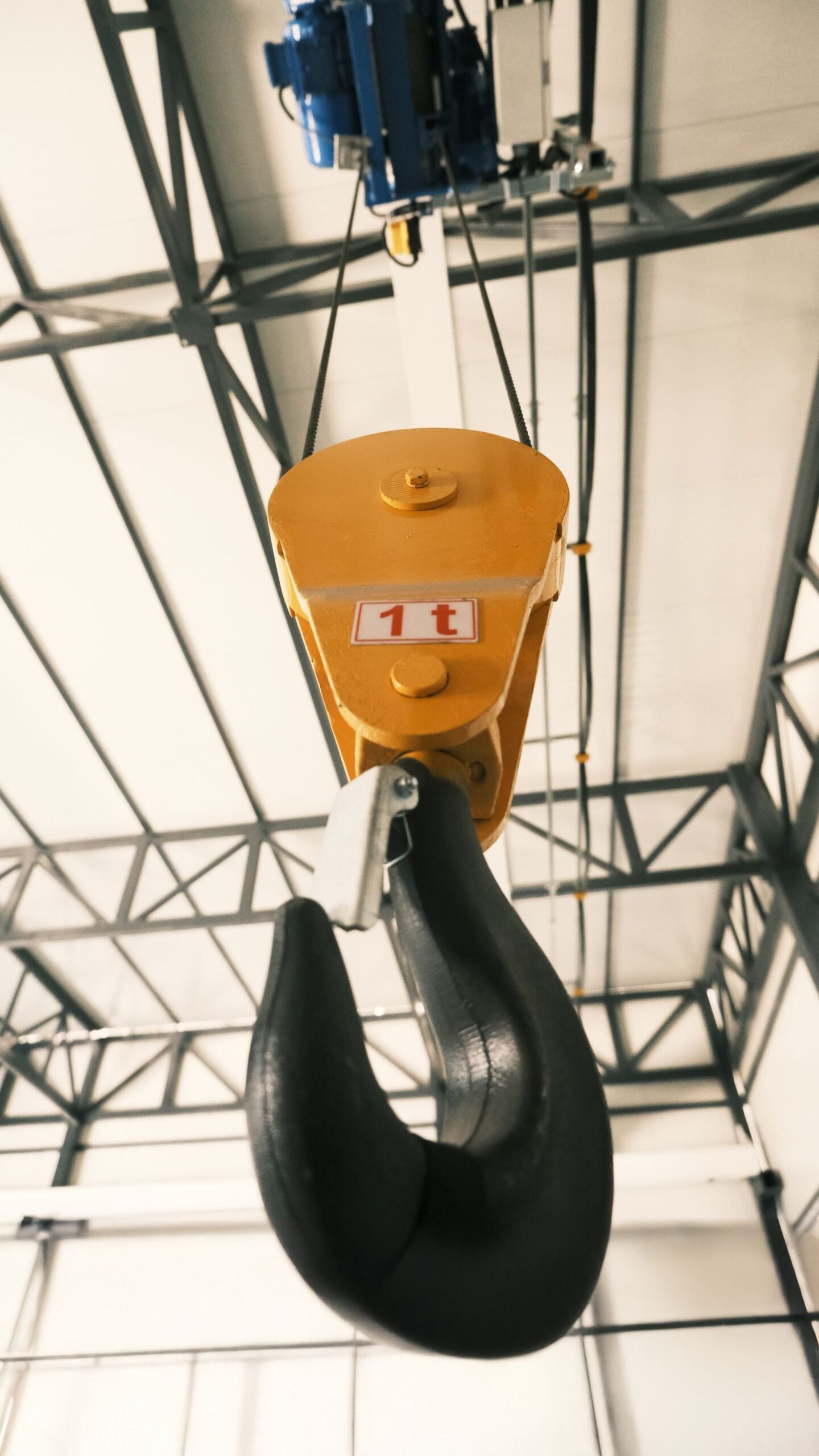
Every wire rope sling carries a tag, and the tag is the final word — the rating that governs the lift, ahead of any chart you read online. OSHA requires slings to be marked with their rated capacity, and a sling with a missing or illegible tag comes out of service. The tag usually shows the vertical rating plus choker, basket and bridle ratings at 60°, 45° and 30° — those bridle numbers already have the angle factor built in.
The hitch multipliers that sit underneath those numbers:
- Vertical hitch: 1.0× — the baseline everything derives from.
- Choker hitch: 0.75× — the bend through its own eye costs about 25% of the vertical rating, and that assumes a choke angle of 120° or more. A tighter choke derates further.
- Basket hitch: 2.0× — two legs of support, but only when the legs run vertical and the D/d ratio at the bend is adequate. The moment the basket legs splay, apply the load angle factor to the doubled figure.
| Angle of choke | Percent of choker rated load (per ASME B30.9) |
|---|---|
| Over 120° | 100% |
| 90°–120° | 87% |
| 60°–89° | 74% |
| 30°–59° | 62% |
| 0°–29° | 49% |
And the angle minimum binds the whole thing together: ASME B30.9 is explicit that slings shall not be used at an angle of loading below 30° from horizontal except as recommended by the sling manufacturer or a qualified person. In practice that means longer slings or a spreader beam — never a shallower angle.
Wire-Rope-Specific Effects of Shallow Angles
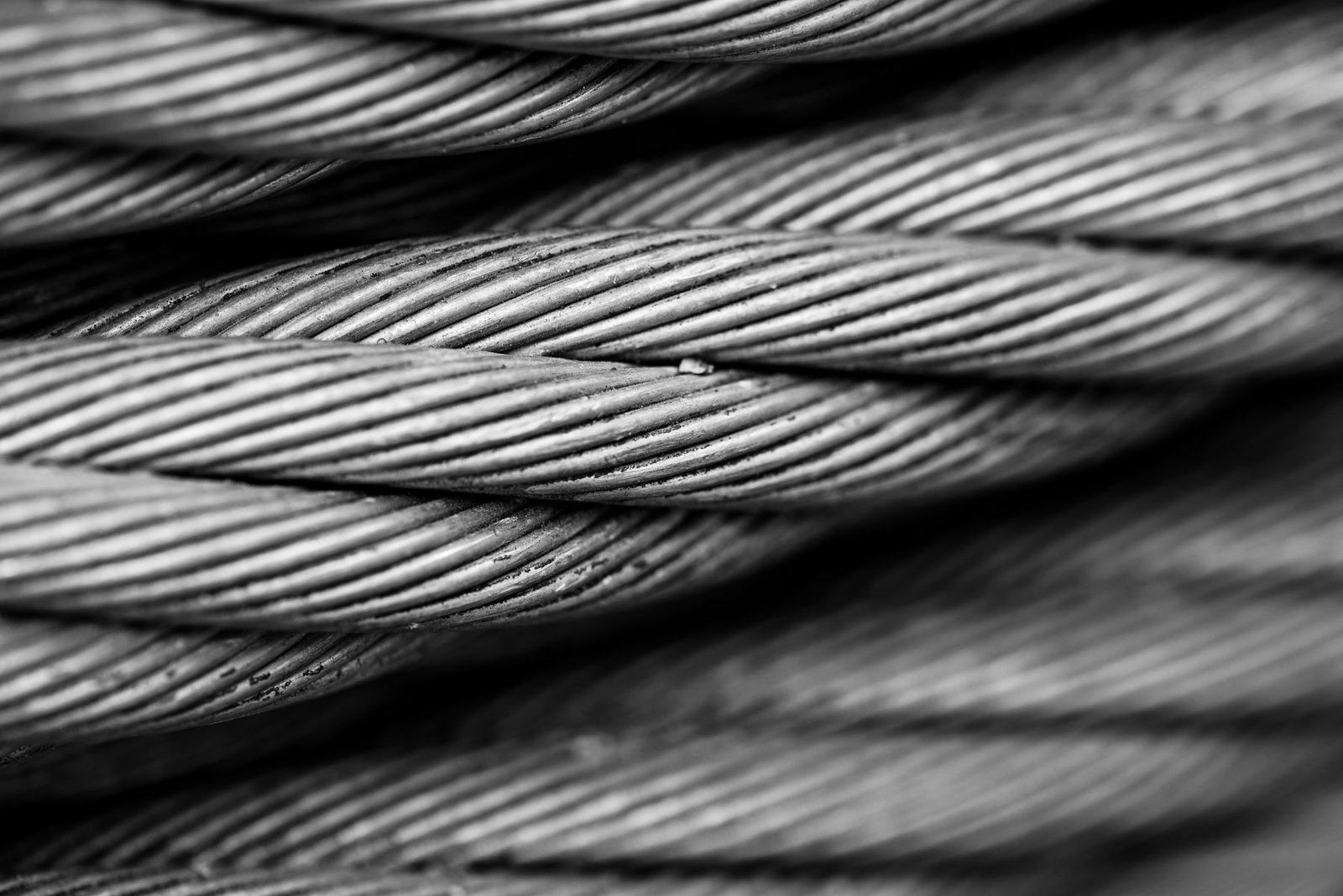
Any sling loses usable capacity at a shallow angle. Wire rope slings add a few effects of their own:
- Bend efficiency at the eyes. The leg tension at a shallow angle passes through the eyes and fittings at a higher value, and a rope bent around a small shackle pin or narrow master link does not deliver its full catalog strength. The D/d ratio — pin or bend diameter divided by rope diameter — governs how much you keep. Generous thimbles and correctly sized hardware are cheap insurance; our rigging hardware guide covers sizing the fittings in the same force path as the legs.
- Design factor is not spare capacity. Wire rope slings typically carry a 5:1 design factor, but that factor covers wear, dynamic loading and the difference between a new sling and the one in your hand — it is not margin you can spend to justify a shallow lift. Our breakdown of the wire rope sling safety factor explains what 5:1 actually covers.
- Uneven loading stresses the splice. On off-center or rigid picks, the overloaded leg works its pressed ferrule or splice hardest — one reason angle-driven overloads show up later as splice-zone damage during sling inspection rather than as a dramatic failure on the day.
- Rotation on long flexible picks. Standard right-hand lay rope in a lightly loaded leg can rotate under tension and loosen the strand pack, most often visible as a “soft” sling body near the eye after repeated off-balance lifts. Grommet constructions sidestep some of this on very heavy picks — see our grommet sling guide.
The common thread: a shallow angle multiplies everything in the force path, not just the rope. When you select sling diameter against the calculated tension, check that the MBL behind the rating is consistent — our guide to breaking strength, MBL and safety factor shows how the numbers on a certificate relate to the tag.
How to Fix a Too-Shallow Angle
When the calculated tension exceeds what the slings can legally carry, you have four levers, in the order I would try them:
- Longer slings. More leg length for the same pick-point spread means a steeper angle. The catch is headroom: longer slings raise the hook.
- A spreader or lifting beam. The standard answer. The beam takes the spread, so the legs hang steep from the hook while the beam spans the pick points — and it takes the horizontal squeeze force off the load entirely.
- Move or add pick points. Bringing attachment points closer together steepens the legs without touching the sling length — sometimes free, if the load accepts new lugs or choker positions.
- Bigger slings. The last resort, not the first. Sizing rope to rescue bad geometry costs money on every future lift; fixing the geometry costs once.
Field Quick-Checks Before the Hook Takes Load
- The 60° check: if the distance between pick points is no more than the leg length, the legs are at 60° or steeper and you are within 1.155 of vertical.
- The L ÷ H habit: tape the leg length and the headroom, divide, and you have the angle factor without a protractor.
- The half-and-half suspicion: any time the hook is not over the CoG, stop assuming even shares and run the lever math.
- The flat-look stop: if the bridle looks flat from the ground, it is already too flat — recalculate before the load leaves the ground.
If a lift plan calls for the same slings on the same load week after week, it pays to spec the assembly once with a manufacturer instead of improvising each time. Aulone is a professional manufacturer and supplier of steel wire ropes, wire rope slings, synthetic ropes and rigging hardware for lifting, marine, mining, construction and industrial applications. With more than 20 years in the trade and an annual capacity of 200,000 tons, we keep common sling constructions in stock and build custom assemblies — eyes, thimbles, ferrules and pendants — with third-party testing available on request. Production runs under EN 12385-4 and ISO 9001, with BV, ABS, DNV, RMRS and CE certification where the application calls for it. Send us the load weight, the pick-point spread and the available headroom, and we will size the assembly and tell you honestly whether the angle works — write to info@wireropes.net.
Frequently Asked Questions
What is the sling angle factor and where does it come from?
It is the multiplier 1 ÷ sin θ, where θ is the sling angle from horizontal. It converts a leg’s share of the load into the actual tension the leg experiences: 1.155 at 60°, 1.414 at 45°, 2.000 at 30°. It comes straight from resolving the leg tension into vertical and horizontal components — no approximation involved.
What is the minimum safe sling angle?
ASME B30.9 sets 30° from horizontal as the floor: below that, slings shall not be used unless the sling manufacturer or a qualified person recommends the configuration. The reason is not just tension — below 30° the horizontal forces grow faster than the tension math suggests, and small errors in measuring the angle produce large errors in load.
Does a shallow angle actually weaken the sling?
No. The rope’s breaking strength is unchanged. What changes is the demand: the geometry forces each leg to carry more tension to support the same vertical load. It is like a longer lever — nothing about the lever changed, only the math on the other side.
How do I measure the sling angle in the field?
Three practical ways: divide leg length by vertical height (L ÷ H gives the factor directly, since sin θ = H ÷ L); use a phone inclinometer app held along the leg; or use the 60° quick check — if the pick-point spread is no greater than the leg length, you are at 60° or steeper. Round any measured angle down to the next chart value.
Why doesn’t a four-leg sling give four times the capacity?
Because a rigid load almost never shares its weight across four legs equally — tolerances, stretch and CoG position leave one or two legs carrying nearly everything. Ratings and conservative practice credit only two legs on a rigid pick, which is why published four-leg ratings commonly match three-leg values, and why ASME B30.9 caps quadruple-leg alloy chain slings at the triple-leg rating.
What is the difference between the sling angle and the included angle?
The sling angle is measured from horizontal between the leg and the ground; the included angle is measured at the hook between the two legs. For a two-leg sling, included angle = 2 × (90° − θ). A 60° sling angle is a 60° included angle; 45° is a 90° included angle; the 30° minimum is a 120° included angle. Check which convention a chart uses before reading a factor from it.
Does the shallow angle damage the load as well as the sling?
It can. The horizontal component of leg tension squeezes the load inward — at 30°, nearly the full load weight per side on a two-leg lift. Crated machinery, thin-walled vessels and lightly braced frames are the usual casualties, and shackles and eyebolts get dragged sideways. A spreader beam removes the squeeze force entirely — a second reason to prefer one over simply buying bigger slings.